Free Download Your Desired Softwares and Apps From GetintoPC
How to Convert 2D to 3D in AutoCAD: A Complete Step-by-Step Guide
AutoCAD can manage 2D drawing, 3D modeling, and everything in between, so you don’t need a different software program to switch. You will primarily prepare the 2D drawing that you want to convert and then switch to a 3D workspace to use tools such as EXTRUDE, PRESSPULL, and REVOLVE in the 3D Modeling workspace. 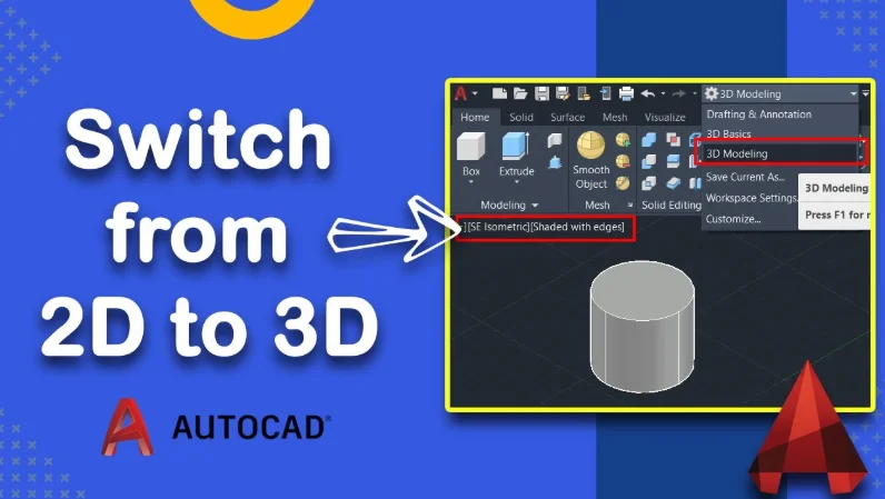
Step 1: Open or Prepare your 2D Drawing
The first step is to open your existing 2D drawing or create a new drawing. When you do this, ensure that your geometry is clean and complete. It means making sure that all of your lines are connecting correctly and that you form closed shapes (i.e., rectangles, circles, or closed polylines). Tip: You can use the JOIN or PEDIT command to connect line segments into closed shapes. AutoCAD requires closed boundaries to extrude them into 3D objects.
Step 2: Change to 3D Workspace
By default, AutoCAD opens in a 2D Drafting workspace, and you will need to change to work in a 3D environment. To do this, follow the steps below:
- Locate the Workspace Switching icon (represented by a gear icon) in the bottom-right corner.
- Select the option labeled ‘3D Modeling‘.
- After changing, your ribbon will reflect the transition from, for example, the 2D Modeling Task Area to the 3D Modeling Task Area, with tools available to manipulate 3D objects, such as Modeling, Mesh, and Visualize.
You can also type the command:
WORKSPACEThen select 3D Modeling from the list. (Tip: If the gear icon isn’t visible, just type WORKSPACE , it’s quicker and does the same thing.)
Step 3: Configure a 3D View
Now that you’ve prepared your 2D shapes, let’s navigate to a 3D view so that you can get a visual representation of your model. You can do this in a few ways:
- Go to the View tab, find the Views panel, and click View Manager.
- Or click on the ViewCube in the top-right-hand corner of your drawing area. Click SW Isometric to get a nice 3D view angle of your drawing.
- Another quick way to do this is to type VPOINT in the command line and type 1,-1,1. This command will also give you an isometric view of your drawing.
Tip: To configure a better visual style for the 3D model, you can edit the visual style. Type VISUALSTYLES, then select Shaded with Edges or whichever visual style works best for you to get more clarity on the model.
Step 4: Using the EXTRUDE Command
It is where we bring your 2D shapes to life! The EXTRUDE command enables you to transform flat shapes into 3D solids by extruding them upward (or along the Z-axis). Here’s how to use the EXTRUDE command: This is the fun part , where your 2D drawing finally turns into a real 3D model.
- Type the command EXTRUDE into the command line or click on the Extrude button on the Modeling tab.
- Select the 2D object you want to extrude geometrically, such as your rectangle layout or blocks (see the closed polyline here).
- Once selected, press Enter to confirm.
- Now, specify the height of the extrusion. You can either drag your cursor upward or type in a value like 50, then press Enter again.
And that’s it! Your flat 2D shape is now a solid 3D object.